The “build tight – ventilate right” concept has been promoted since the eighties; the current Approved Document L for England and Wales sets the air permeability target for new dwellings at 10m3/hm2 at 50Pa. Reducing air permeability – in other words, uncontrolled air leakage – is a cost-effective means to improve energy efficiency. Indeed, the Passivhaus house standard requires an air permeability index of 1m3/hm2 at 50Pa.
Achieving low levels of air leakage requires measures for air permeability to be included in the design strategy and for these measures to be installed as planned. This requires a level of care that is not always maintained. For buildings that have not been designed with air permeability in mind, high levels of heat loss caused by uncontrolled air leakage of greater than 25% have been observed on exposed sites.
Air leakage is not just about wasted energy. Gaps in the fabric allow the passage of warm moist air to flow from the inside to outer, cooler layers; surface and interstitial condensation may result, leading to potential damage to the building fabric as well as reduced U-values.
Investigating air-tightness
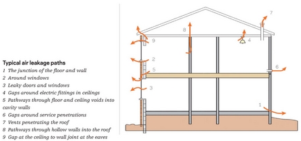
There is plenty of guidance listing uncontrolled air flow routes. Uncontrolled air flows and consequent heat loss occur mainly though gaps in the construction. Gaps occur, generally at junctions between dissimilar materials and assemblies. A convenient classification of leakage paths includes:
- Gaps between components, such as between external door leaf and door jamb or door jamb and external wall
- Gaps between elements – for example, upper floor and external wall
- Gaps resulting from service penetrations through the building envelop such as pipes, flues or lift shaft
- Permeable building materials such as lightweight blockwork.
You’ll probably be on a hiding to nothing trying to find air flow paths by visual inspection. Although some routes may be obvious – such as ill-fitting windows – other routes are complex such as those behind drylinings, gaps hidden by fitting and finishes and in particular routes through wall cavities and masonry perpend joints.

Typical air leakage paths
Observation of the construction and feeling for draughts may give an indication of the problem areas but will be no substitute for a controlled building air permeability test which will be able to quantify the before and after air permeability performance.
Air-tightness testing should be carried out to the Air-Tightness Testing and Measurement Association’s (ATTMA) Technical Standard 1 and the results expressed as an air leakage index: m3/hm2; the volume of air leaking out of a building as a ratio of external envelop area (including ground floor area) at a 50Pa reference pressure difference between the inside and outside of the building.
A suitable fan should be installed and the building prepared to BS EN 13829 for fan pressurisation. Method B is generally used, which involves closing all external openings, opening all internal doors, heating, ventilation and air-conditioning systems turned off and related openings sealed.
A positive or negative pressure is applied to the building. A computerised control system is used to maintain a constant pressure difference. Air leakage sites can be identified with a smoke pen or tracer gasses. Other diagnostic tools to measure and document air flow include infrared thermal imaging cameras to identify cool spots resulting from air flows; an anemometer can be used to quantify the air flow rates.
Remedial work
Remedial work may simply be a case of filling in the gaps. Typically this might involve the application of sealants, but allowance should be made for future thermal and moisture movement.
Components for residential buildings that bridge the air permeability layer, such as downlighters in ceilings below cold roofs, should be tested to BS EN 13141-1, the standard for performance testing of components for residential ventilation, to demonstrate air leakage rates meet recommended levels.
BS 9250 provides guidance on methods to achieve “well sealed ceilings” for cold and warm pitched roofs.
Condensation risk
Assessing the risk of condensation resulting from airflows is complex. BS EN ISO 13788 is the calculation method referred to in the standard for condensation (BS 5250) – this, however, excludes airflow considerations. BRE has developed a software model to assess the risk of condensation in cold roof spaces (RoofCond).
An interesting observation from the research on air-tightness is that buildings that have dried out are more likely to be leaky than new build. Once the construction moisture has been driven off and the fabric dried out, gaps appear around components. This does beg the question of the lifecycle effects on buildings that are designed to be highly airtight.
For good practice guidance and research information, refer to publications from BRE, BSRIA, and CIBSE while the communities department provides accredited construction details which minimise air leakage.


